The Andor BoB (Breakout Box) is available in two models:
BoB-D provides only digital (TTL) inputs and outputs. It is usually connected to a Measurement Computing DIO24 PCI card in the computer.
BoB-A provides digital (TTL) inputs and outputs, as well as an analogue (0-10 V) http://output.It is usually connected to a Measurement Computing DDAO6/16 PCI card in the computer.
The latest models of both BoBs are also "gated" or "buffered". This means that some, or all, of their digital (TTL) outputs are synchronised, using a logical AND, to an input.
For example, if there is a "Gate B" BNC connection present on the BoB, it will be linked to the output of "Output B". In order to issue an output (high TTL) on "Output B", there must be an input (high TTL) signal supplied to "Gate B" AND a software instruction to output (high TTL) on "Output B". This is most often used to synchronise a fast light source (e.g. LED) to the camera's Fire signal, for example to improve the quality of transmitted light when used with a spinning disk. This is very similar in concept to "Active Blanking" on the ALC (Andor Laser Combiner) and ILE (Integrated Laser Engine).
The BoB can be added to the active devices in the Device Hub:
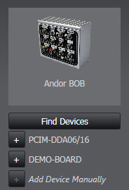
Clicking "Find Devices" will show any supported DAC (digital/analogue control) boards present.
This device depends on the Measurement Computing software, InstaCal 6.5. If this is not installed and configured, the device will not be found by Device Hub.
Please download, install and run InstaCal 6.5 from here.
Once added, the following features will become available elsewhere in the software:
Brightfield Trigger
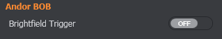
Default Location: Channel
Default Setting: Off
When enabled, this will set Output B of the BoB high whenever that imaging mode is used.
For example, the user could create a new Image Mode called "Transmitted" or "DIC" and enable this setting. On a gated BoB, this would result in Output B going high when the image mode is used AND when the system is Live / running a Protocol. (Because it is dependent on also receiving an input on "Gate B", which should be connected to the camera(s)' Fire (if EMCCD) or Aux Out 1 (if sCMOS) signal.
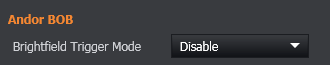
Brightfield Trigger Mode
Default Location: Advanced
Default Setting: Disable
When set to Open/Close, and the system is imaging, turn on a shutter or light source that is connected to Output B of the BoB device (dependent on the camera being live) or Output 4 of PCU device.
Feature Locations
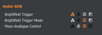
The location of these features can be changed in the Channel, Image Mode, Feature Locations section.
Selecting 'spare' output for device action
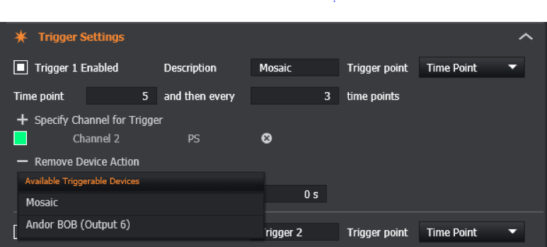
When a BoB device is connected, the 'spare' BoB output can be selected as the device action for a Trigger in the 'Trigger Settings' specification on the Protocol Manager Tab. This is typically Output 6 or 7.
This shall issue an output (TTL) on the corresponding output when triggered.