Most samples are not entirely flat. This may be from the sample itself and how that has been prepared, the microscope slide or multi-well plate, or a degree of tilt to the stage. This is normally acceptable for imaging, but can be an issue for some experiments. Fusion provides the ability to correct the focus across uneven samples (both simple and complex) using Focus Map for both 2D and 3D imaging. Options are provided for Global or local Focus maps.
-
Global Focus Map applies a single focus map across one area i.e. within a single field of view (including montage).
-
Local Focus Map option enables focus maps to be created for each field within a multi-field protocol e.g. for a multi-well plate
To see how to create a protocol with a time series see Creating a Time Series Protocol.
To create a protocol that includes a montage (image created with multiple adjacent fields of view) see Creating a Montage for more details.
When would applying a Focus Map be useful?
Applying a focus map may be most useful for confocal imaging using high NA higher magnification objectives as the focal depth is is tightly constrained. The brightness of the image will sharply drop off outside of the focal plane, and so across a larger specimen, there may be a gradient in intensity, areas may appear dim, or not visible. By using a focus map this can be corrected so that the image remains of uniform intensity and in focus across larger areas. For widefield imaging, and/or using lower NA, lower magnifications the effects of an uneven sample are less significant as the focus is not so tightly constrained. A focus map would therefore not be required under such conditions.
Tilt Correction using Focus Map
Enabling Focus Map
Focus map can be enabled by selecting the Enable Focus Map button.
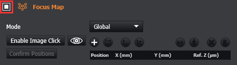
Global/Local Mode
-
In Global mode, a single focus map will be used for all field/well positions.
-
In Local mode, a separate focus map can be defined for each field/well in turn. Select a field position/well from the multi-position table, or the Well Navigation section. The currently-selected position is noted in the Focus Map section.
In both modes, all field/well positions should be set up with good focus which serves as the “anchor point” or reference focus. The focus map will be created to maintain this focus level across the montage.
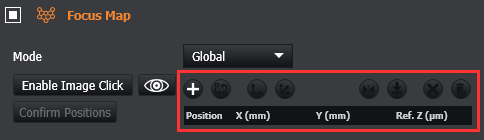
Adding Focus Map Positions
There are 2 ways to add a focus map position:
-
Add via the table.
-
Add position(s) via image click
Adding via the table
To add focus map positions via the table, first enable the focus map in the protocol.
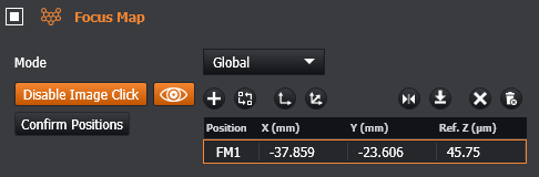
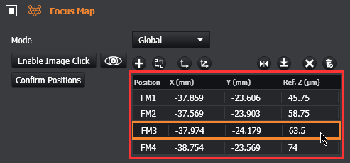
Each Focus Map position has the following information:
-
Position: this is the number of the chosen XYZ position.
-
X (mm): the X coordinate of the XY stage/image
-
Y (mm): the Y coordinate of the XY stage/image
-
Ref. Z: the Z position (focus) of the microscope for this position. When using the Piezo for Z Scans, this will be the centre of the stack.
Guidelines
-
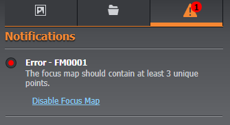
At least 3 unique positions are needed to complete a valid focus map.
-
The number of positions required for the focus map will depend on the complexity of the sample e.g. correcting for focus in the x axis only would require less points than a sample with folds, curvature or other complex variations.
-
For simple corrections e.g. linear such as correction in x or y use a minimum of 3 positions
-
For more complex corrections, it is recommended to include positions around the perimeter of the montage area.
-
Add more points in regions where focus changes more sharply, and less when it is a more gradual change in focus.
-
If the focus map is enabled with less than 3 positions defined, a problem notification will appear (shown below) and the acquire button will be disabled so that this can be rectified.
-
If switching between objectives note that focus may require a slight adjustment to correct focus.
-
When more than 3 points are provided, all field/well positions should lie within the polygon boundary for best results.
-
In Local mode, each local map likewise must have at least 3 unique points.
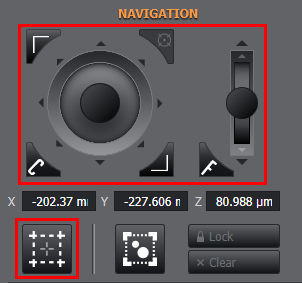
To add a position, navigate with the software or hardware joystick and choose the focus position with the microscope. Alternatively, enable 'Click-to-go-to' mode from the remote panel to manually select positions from the image display.
Click the + button to add the current stage position to the table.
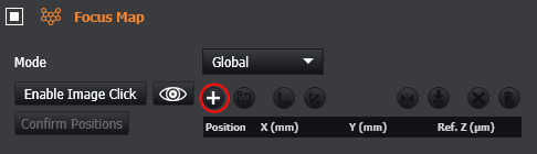
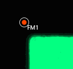
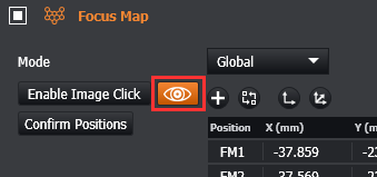
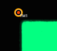
Focus map definitions can be viewed on the image panel when 'Enable Image Click' is enabled from the focus map protocol specification.
Each position defined will have its corresponding table position labelled beside the marker on the image.
Adding via Image Click mode
To add focus map positions, enable the focus map section in the protocol.
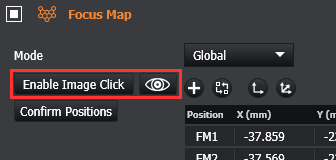
With the focus map section enabled click on the ‘Enable Image Click’ button.
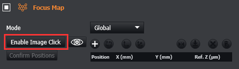
Now you will be able to navigate through and across the sample and manually select each focus map position as required.
The added focus map position will now also appear in the table.
Viewing Focus Map Positions
After positions have been set for focus map, you can view them as points within the image display using the ‘View Focus Map Positions’ button.
Local Focus Maps
Local Focus Maps can be configured for multi-position protocols so that the areas within each region are accurately mapped. This option is only available when a multi-position protocol has been selected.
-
If using a microscope slide, positions must be defined.
-
If using a well-plate, at least one well must be selected.
When all of the required positions/wells are defined, a focus map can be defined for each position/well using the same process previously described for a Global Focus Map.
Navigating between each of the positions/wells in the multi-position protocol panel will select it in the Focus Map panel. Focus Map positions can then be added to the focus map table using the 'Image Click' functionality or stage move and 'Add' button.
When you are happy with the positions defined in XY, you can go through and review each position to adjust to an appropriate Z for optimal focus. This should be repeated for each of the multi-position/multi-well position defined. If any well/position does not have a local focus map defined, an error notification will appear and acquisition cannot run.
Selecting Focus Map Positions
To Select a focus map position there are 2 methods available.
-
Select via the table.
-
Select the position via the display
Selecting via the table
To select Focus Map Positions through the table, click on the appropriate row:
Optionally you can CTRL + Click to select multiple rows.
Selecting the position via the display
Enable Image click mode or toggle the ‘View Focus Map Positions’ button, so you can see and select each Focus Map position.
Each focus map position becomes visible in the image once Enable Image Click has been selected.
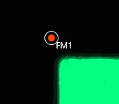
Now you will be able to click on these positions.
When you select a position, the table row will be highlighted. Note that when selecting focus map positions through the display, selecting multiple positions at a time is not possible.
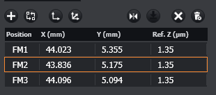
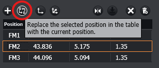
Replacing Focus Map Positions
A focus map position in the table can be replaced and updated to the current stage position if desired:
-
Select the position to replace.
-
Move to the desired position using the joystick or 'go-to' functionality.
-
Replace the position values with the current position values.
|
|
|
|
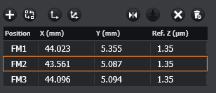
The table and image display should now be updated to reflect the new values for the replaced position.
Using the ‘review and go-to’ shortcut CTRL + . the stage will move through each focus map position. Moving the stage manually and then pressing CTRL + . will update the position.
Apply current XY offset
Click offset current XY button to update the values for the selected position in the table with the current X and Y values. This will then update every position in the table to apply the same offset to each one. e.g. this could be applicable to a multi-well plate.
Apply current XYZ offset
Click offset current XYZ button to update the values for the selected position in the table with the current X, Y and Z values. This will then update every position in the table to apply the same offset to each one.
Go to position
Click the Go to Selected position button to jump to the position selected. When the stage moves to the current selected position, a thick orange border will appear around the row in the table.
Alternatively, double click on a row to jump to the position.
Go to next position
Click the Go to Next position button to move to the next position in the table.
Delete selected positions
Select any row/position in the table you wish to remove from the table. When all rows are selected, click Delete and confirm you are happy to proceed with deletion. Note that you can use Ctrl + Click to select multiple rows.
Delete all positions
To delete the entire contents of the table, click the Delete All button. You will be prompted to confirm deletion of the entire table.
Clear All Focus Maps
In Local mode, this button will delete all focus map points in all local map tables. Confirmation is required before any data is deleted.
Confirm Positions
The Confirm Positions button lets you interactively review and update the z positions of the focus map points before running the protocol. Each click of the confirm button will update the z position of the active focus map point to that of the current stage position and will then move the stage automatically to the next focus map point position for review.
Video Tutorials can be found here: Focus Map