Using the Navigation functions
The specimen can be navigated through the X, Y and Z axis using the on-screen joystick functions. An overview of the navigation settings is shown in Navigation.
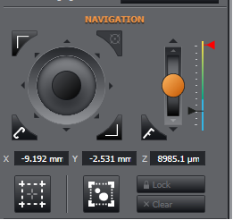
Using the Joystick to navigate through X and Y axes
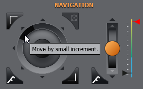
The joystick can be used to move the stage through the X and Y axes. A small sub window appears in the main image viewing window showing the stage position.
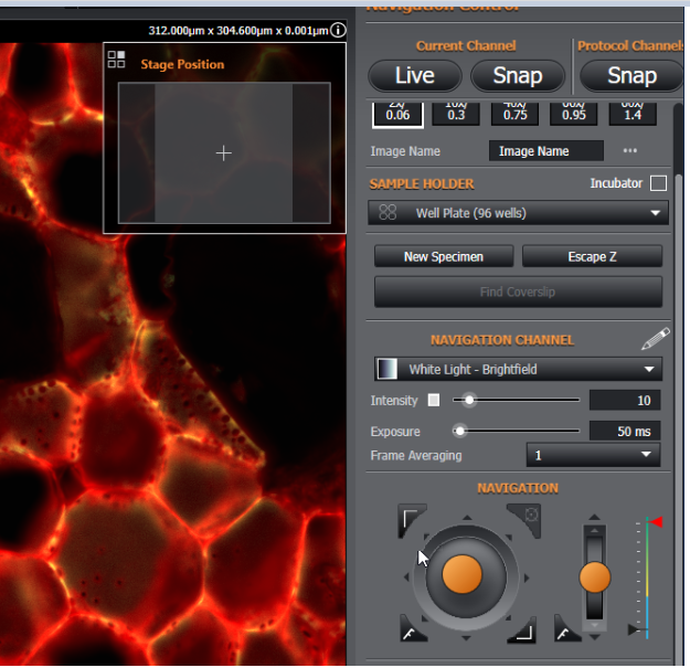
Above - Using the on-screen joystick for navigation. Note the sub-window showing the current stage position.
A video guide can be seen here: Sample Navigation
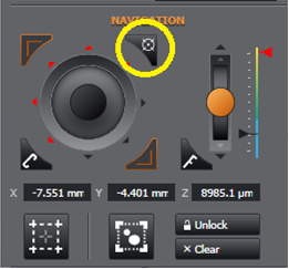
The position of the Stage Position sub-window can be adjusted to appear in a different corner of the image viewer panel. To do this, click the highlighted icon below to cycle through the four corners of the image. Alternatively you can right click to select from a drop down list.
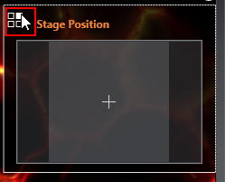
Above - Setting the position of the sub-window, shown from left to right: top left, top right (default), bottom left, bottom right.
The speed of the XY joystick can be set between the coarse (faster), fine (slower) or Superfine (precise) movement. Click the button to select between these 3 options.
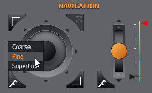
Above - Speed settings for the XY joystick.
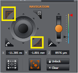
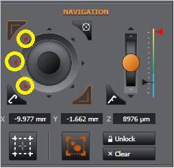
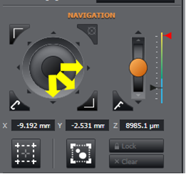
You can also use the nudge function keys around the joystick to move the stage in a large, or small increments:
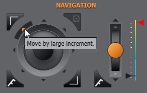
Above Top: the large nudge buttons around the outer ring. Above Bottom: the small nudge buttons around the inner ring. Values for these can be set in navigation preferences.
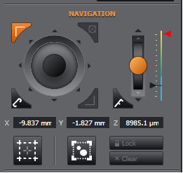
Navigating through the Z-axis
It is also possible to manually navigate through the Z- axis using the Z-axis joystick or the z axis heatmap slider
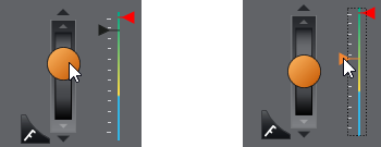
Above Left- Using the Z joystick. Above Right: Using the Z Heatmap Slider
As with the XY joystick, you can also use the nudge function keys above and below the Z-axis joystick to move the stage in a large, or small increments:
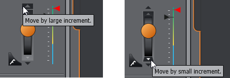
Above Left: The large nudge key and Above Right: the small nudge key. Values for these can be set in Navigation.
The heatmap allows more direct control of the Z stage by clicking and dragging the black slider. The heatmap is designed to give an general overview of when the sample is likely to be in focus.
|
Blue |
Unlikely to be in focus |
|
Yellow |
Less likely to be in focus |
|
Green |
More likely to be in Focus |
The red slider is used to set the maximum position that can be navigated in Z. This is used to reduce the likelihood of crashing your objective into the stage. It can be set by simply dragging the red slider. Z Movement will be limited to this position. This value is saved per sample holder, so each different type of sample holder can have a different safe z position.
A video guide can be seen here : Adding and Cleaning Oil

Setting Bounds
There are two ways to set bounds.
-
Setting a region based on a low magnification image which you will later explore the sample at a higher magnification. The low magnification image could be, for example, a "snap" at 2x or 10x, or if your sample is bigger than the objective can cover then from the image created from a "Specimen Overview" of n images in X by n images in Y (e.g. Width and Height of 8 fields).
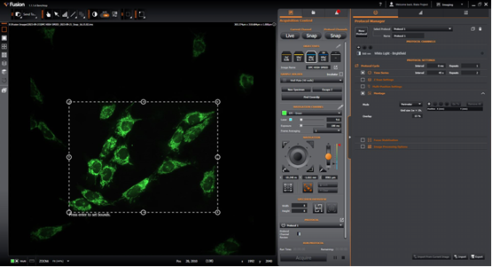
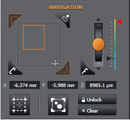
Adjust the bounds perimeter to your required size by dragging the corner and middle edge points. You can move the bounding region by left mouse-drag from anywhere inside the bounded region.
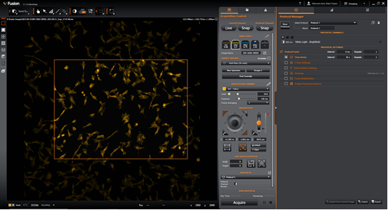
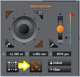
Press enter to lock the bounds in, the perimeter will turn orange.
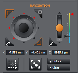
When the bounds are set you see that the top-left and top-right boundary-set (another method to set bounds - see below) turn red. You will no longer be able to drive the stage beyond the set boundary. Should you try, you will see the nudge arrows turn red indicating you cannot travel beyond this point.
If you wish to adjust this perimeter to go beyond this point, you need to click "Unlock". You will see the nudge arrows are no longer red and your bottom-right limit is now bright red indicating you can now move beyond the original set bound. At this point you could choose a new bottom-right limit to re-size your original boundary if you wish.
Should you want to re-establish a new boundary it is advised to "Clear" the current one and start again.
2. Setting your bounds on-the-fly whilst scanning your sample (e.g. following the perimeter of a sample or a structure within a sample). In this case we set a top-left and bottom-right limit and a square/rectangular boundary is established from those two coordinates.
Start with no bounds set. Click "Clear" if necessary.
Next move your stage in joystick in a south and/or east direction.
When you reach your desired limit, click the top-left boundary-set button which will turn solid orange.
Double clicking will not remove the bound - you need to move away from the area to clear or reset.
Now move the joystick in a north and/or west direction and click the bottom-right boundary-set button. Now you will see both buttons in pale orange. This indicates your boundary is set.
Note that there is a "stage view" toggle button which helps you understand where you are relative to the bounded region you set. You can also click the mouse cursor in this interface to jump to stage positions from here. This tool can be helpful if you unlock the bounds and travel out of the bounded region and need to find your way back.

Specimen Overview

Quick WxH Montage: this expands the image on the existing specimen overview, or creates a new specimen overview dataset if one does not already exist.
-
Clicking the button will take a spiral montage of the sample of the specified width and height (e.g. 3 x3) around the current stage position.
-
Moving the stage to a new position and clicking the button will add the montage from the new position to the existing specimen overview so that the image of the specimen can be built up incrementally.
-
If the button is clicked more than once without moving the stage between clicks, then the montage at that stage position will be expanded by one tile in each direction.
-
Note that changing to a different channel and clicking the button will result in the entire specimen image being cleared and restarted with the new channel.
-
When using Quick Montage, only the montage tiles that are not already present in the specimen overview will be imaged.
![]()
![]()
![]()
Quick bounded montage: This will run a quick montage on the area within the stage bounds. It is similar to the Quick WxH Montage, however it will acquire as many tiles as are needed to image the entire bounded area. Only available after bounds have been set.
Note: Further montage options can be defined using a Montage