See also Stitching for details on stitching montage images.
Montage
A series of images can be acquired with each adjacent image overlapping slightly with neighbouring images, allowing a single montage image to be created from the series of smaller images. These can be stitched together so that small variations in position can be corrected and along with the uniform illumination of the system, a single seamless image can be obtained without visible joins. This can be very useful for capturing high resolution images of samples that are much larger than can be acquired from a single field of view. An image montage can be added to a Time Series or a Z-stack Protocol.
There are two ways to define a Montage:
-
Perimeter: lets the outer limits of the sample be defined. This can be suitable for irregular shaped, or elongated samples.
-
Tiles: set a number of image tiles around a central point of interest. Useful for samples with a more uniform dimensions.
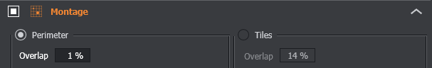
Overlap - Define the percentage of overlap between two adjacent fields. (Note: this option is available in both modes)
Defining by Tiles
In this mode, the size of the montage is defined by the number of tiles. A tile corresponds to the size of the image seen by the camera (full array or cropped to a selected region of interest) and magnification being used.
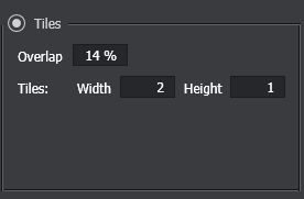
Width/Height - Define the size of the montage as the number of overlapping fields.
Note: If you have bounds set, your montage will automatically adjust Width and Height to fit within the bounds.
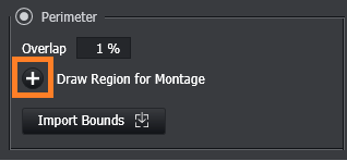
Defining by Perimeter (with Irregular Montage)
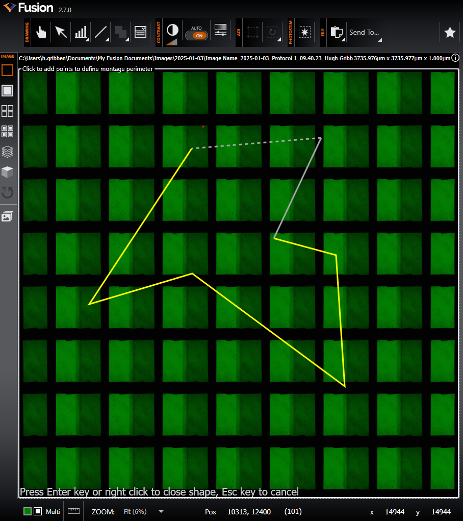
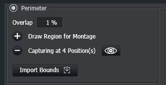
In this mode, the size and shape of the montage is defined by drawing a perimeter on the display via the '+' button on the specification. All of the area within the defined perimeter should be captured when subsequently running the protocol.
Once the perimeter has been defined, the number of positions to be captured shall be provided:
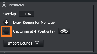
The currently set perimeter can be removed by hitting the '-' button:
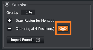
Preview Perimeter - Once you have a Montage Position the Preview Perimeter button becomes active.
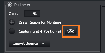
Once this button is clicked a preview of the Perimeter will be shown in the viewer.
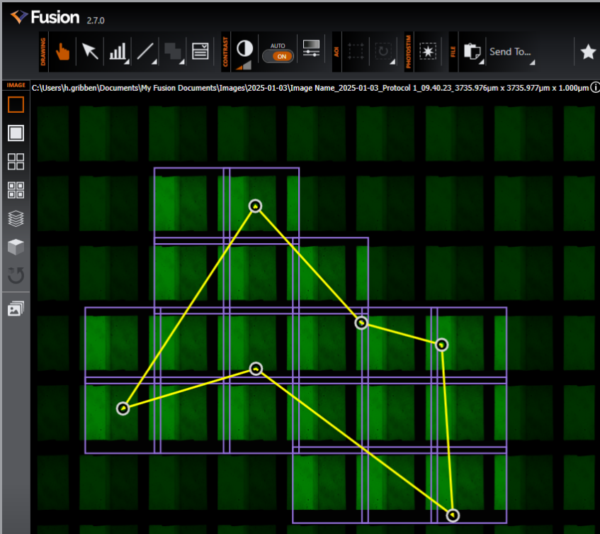
Note: The Perimeter can be modified using the perimeter handles, and the tiles to be acquired based on the current perimeter are shown in purple (note the 10% overlap in the tiles in the shown example)
Click again to hide the Perimeter Preview.
Using Set Bounds in defining a montage
See Specimen Navigation for more detail on setting bounds.
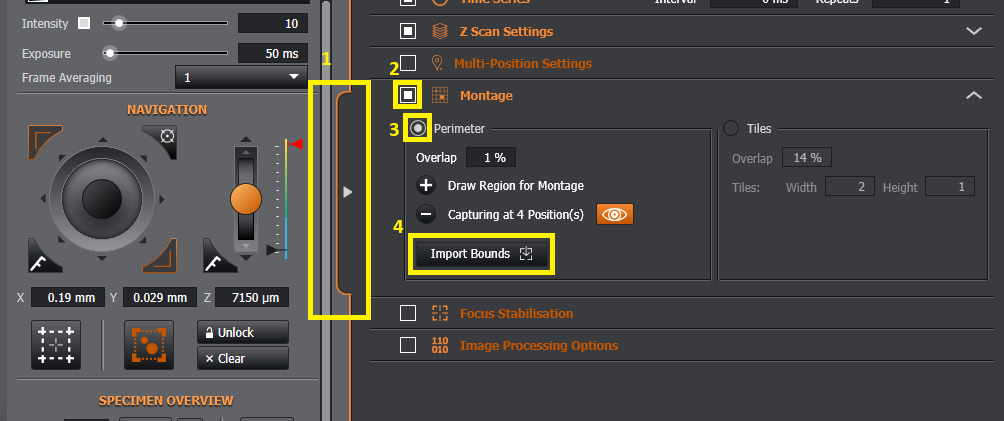
Once your bounded area is set, it is possible to use this as a defined region in which to create a high-quality tiled and stitched image. If you open the protocol tab (1), select Montage (2), select Perimeter (3) you can then import (4) the bounded region to define your montage region.
Note it is not possible to use set bounds when defining a per-position montage.
Defining by Perimeter (without Irregular Montage)
If an Irregular Montage license is not found, then the perimeter functionality shall default to allow the user to specify a 'regular' montage by perimeter.
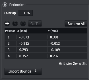
In this mode, the size of the montage is defined by adding two or more fields to the list, similar to the operation of Multi-Position.
Navigate using any of the specimen navigation functionality (Specimen Navigation) to the edge of the sample and click the + button, shown below, to add two or more fields.
Note - the image axes in Fusion and Imaris originate from the lower left corner. As a result, when opened in other software, the montage order may be different to that shown here. See also Image Tools for a description of this.
Images acquired using Montage can be stitched after acquisition. See Andor Stitcher
Alternatively, stitching can also be done in a variety of 3rd party software - for example, Terastitcher, XUVTools and FIJI's Grid/Collection stitching plugin. Please refer to those software packages for instructions on how to combine the images into a complete montage.
A video guide can be seen here: Image acquisition: Acquire a Montage (set tiles) / Image acquisition: Acquire a Montage (set perimeter) (Note: Video applies to versions before 2.7 release)
Video Tutorials here: Irregular Montage & Multiple Irregular Montage