Most samples are not entirely flat. This may be from the sample itself and how that has been prepared, the microscope slide or multi-well plate, or a degree of tilt to the stage. This is normally acceptable for imaging, but can be an issue for some experiments.
Fusion provides the ability to apply offsets to Multi-Position or Multi-Well protocols, and in some cases can work with Focus Map in a Montage.
Overview
Why three points?
-
One point gives a location.
-
Two points define a line, which has direction.
-
Three points define a plane, which allows us to calculate the tilt (angle) of that surface.
Three points can define linear tilt (flat). More than three points can be used for non-linear tilt. It is recommended to use at least 5 points for more complex tilt correction.
What is the best placement of points?
-
Placing points at the extremes of your sample will provide the best correction.
-
Drawing lines connecting the points should result in a triangle with a large area covering the sample.
In the examples tilt is mostly horizontal, so having points as far to the left and right will provide the best correction. The tilt you are correcting for may be angled differently.
What about well plates?
The same principles apply to well plates.
You can use well positions to correct tilt, but keep in mind larger distances between points will provide the best correction. If possible you should use the outer wells for tilt correction.
If you require correcting tilt for each well, defining a local Focus Map in each well position may provide the best results.
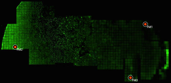
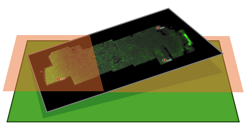
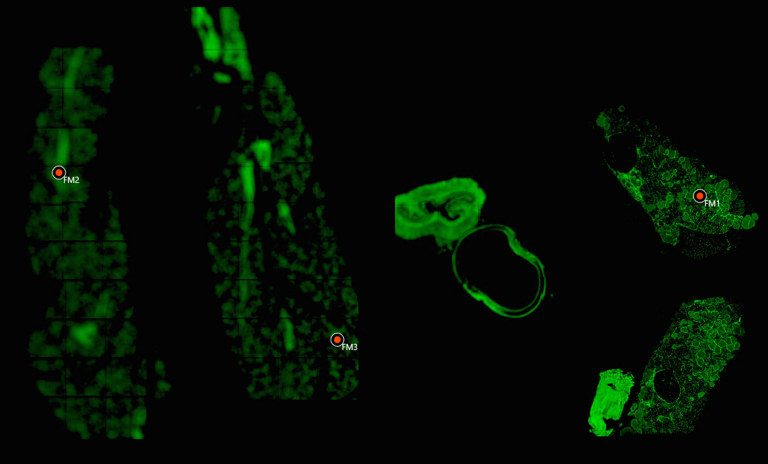
Below are exaggerated examples of tilt, seen in a sample.
The points (FM1, FM2, FM3) in each image were used to correct tilt.
Setup
To setup tilt correction you must define a global Focus Map. It’s recommended to use 3 points as the tilt offset should form a flat surface.
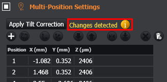
With a focus map defined, you can apply the correction offsets to your multi-position/multi-well protocols using the 'Apply Tilt Correction' button found above the multi-position table, or the multi-well grid.
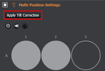
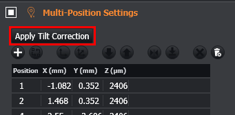
After applying tilt correction, the Z coordinate of the positions in the multi-position protocol will have been updated using the correction offsets. The change can be seen in the multi-position table, and a status message beside the 'Apply Tilt Correction' button will appear.
Using Tilt Corrected Multi-Position with Montage
If you have applied tilt correction to your multi-position protocol, you can still perform a montage at each position. By keeping the global Focus Map used to define the tilt, montages will use this.
Changing Positions or Re-Defining Tilt After Correction
Changing multi-positions
Changing (adding/removing/updating) positions in the multi-position protocol will cause a prompt to show, providing a reminder to re-apply the tilt correction if required.
Clicking the ‘Apply Tilt Correction’ button will reapply tilt correction offsets to each position.
Re-defining tilt
You can update tilt correction by clicking the ‘Apply Tilt Correction' button again after defining a new global Focus Map