The Mosaic needs to be calibrated so that illumination positions on the Mosaic DMD array are mapped to the pixel positions of the image. This will need to be performed to match the imaging setup that will be used for precise optical alignment and accurate mapping. Note that changing illumination e.g. Mosaic Diode laser, or HLE, microscope cubes, or using different wavelengths for the HLE or LED illumination e.g. 405nm laser to 785nm would affect optical alignment. Changing beamsplitter plugs do not impact the calibration. Mosaic calibration will also apply to a second camera that was not used for the calibration. The Calibration process on the Mosaic is automated making it fast and easy to obtain a good calibration. The calibration is based on a series of known spot co-ordinates on the DMD running in a sequence. A spot detection algorithm then runs to allow mapping to the on-screen pixels and bounds of the area of photostimulation to be defined.
Selecting a Suitable Slide for Calibration
A uniform slide that can fluoresce is required for calibration. It the sample bleaches, this can have further uses for troubleshooting. Some examples are outlined below:
-
Andor FRAPPA calibration slide (Part No. XS-AND-001). This will fluoresce and photobleach. Ideal for calibration, as well as alignment checks and troubleshooting purposes as a sharp resolution is possible.
-
Fluorescent Microscope Slide – plastic fluorescent slides are available from many suppliers and these are suitable for calibration. Examples include: FSK2, FSK3 slides (also part of FSK5, 5 slide pack), (Thorlabs) or 92001 Autofluorescent Plastic Slides (Chroma). Note that the edge of the test pattern will not be sharp as with the FRAPPA slide, since the full thickness of the slide is made of homogeneous fluorescent material making it not suitable for alignment checks, or other troubleshooting.
-
Fluorescent "highlighter" slide can be prepared and are practical, yet effective. Note that some fluorescent highlighter marker pens use dyes that are resistant to bleaching and can be used for calibration only. A suitable, widely available example that will bleach, is a yellow or green Stabilo Boss Original model. This is bright and will readily photobleach even at lower powers such as with LED illumination. It is therefore very good for calibration and troubleshooting. To prepare a slide, apply the marker pen evenly over a region of the surface of normal microscope slide (e.g. over an area of ~1cm x 1cm). A coverslip can be used and fixed in place using fast drying nail polish, or other suitable fixative as is used for routine slide preparation.
-
Alternative fluorescent samples could be used for calibration if they have a uniform region over the photostimulation area of the Mosaic. Using a sample with structure can cause calibration to fail as spots would not appear in areas that do not fluoresce. Therefore, it is recommended to use the FRAPPA calibration slide, or the fluorescent microscope, or highlighter slides where possible. A sample that you know you can photobleach can be useful for troubleshooting e.g. to check photostimulation illumination is reaching the specimen.
-
Mirror Slide (MSC-05051) since it is a mirror slide it won't photobleach, but it is useful for checking alignment and focus when using LED/white light sources. Readily available from Andor.
Calibrating Mosaic
-
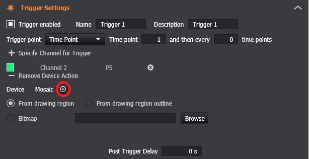
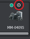
Open the Mosaic Calibration Panel. This can be opened/closed by clicking on the calibrate button located at the top of the Mosaic device in the Active Devices panel (right corner of screen) and within the Trigger Settings in the Protocol Manager tab. Note that the Mosaic must be connected in device manager for this to be available.
-
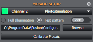
Select the photostimulation channel to be used from the calibration panel (only current channels with Imaging Mode type 'Photostimulation' are selectable). If one is not available, go to the channel manager and create a new Photostimulation channel in the same process as any imaging channel. Note it is recommended you use a calibration channel that has laser power, mosaic illumination time and camera exposures times that provide a good signal for calibration. The settings you will use for a real specimen will not be the same as is required for calibration.
-
Confirm the light path is passing through to the detector, and adjust focus using the manual illumination options under Mosaic setup:
Full Illumination - Illuminates the full mosaic array. Depending on model and the light sources the size and shape of the array will vary- but it should have a clear and smooth edge in all cases.
Test Pattern - Illuminates the mosaic array using a selected bitmap (.bmp) image file containing a test pattern as a source. A default bitmap file is available at C:\ProgramData\Fusion\Configuration\PhotostimulationBitmaps.
-
Adjust the focus so the selected test pattern is resolved. The selected illumination (when in Live mode) can be viewed by using the toggle on / off button in order to view either the full illumination or the test pattern.
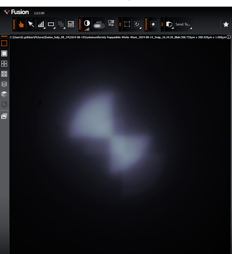
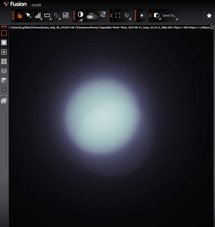
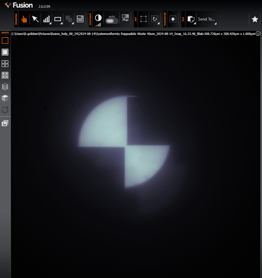
Example of out of focus Mosaic illumination (full illumination and test pattern):
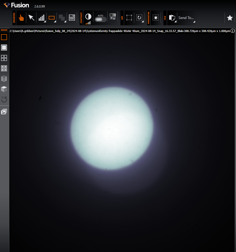
Example of in focus Mosaic illumination (full illumination and test pattern):
-
Once you find an acceptable focus, click the Calibrate Mosaic button to start the automatic Mosaic Calibration process. This generates images from spot-shaped illumination patterns with known positions on the Mosaic DMD array, and automatically calculates the pixel positions of the associated output spot structures in the images. While the calibration is running it will override any previously manually selected full illumination, or test pattern.
-
Once complete, a message will be displayed on-screen to show a successful or unsuccessful calibration.
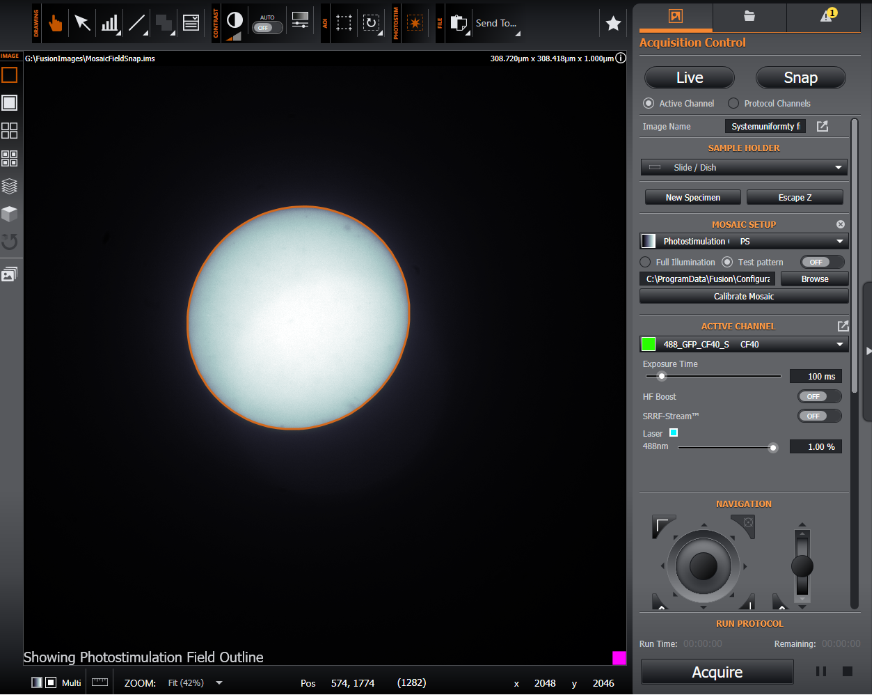
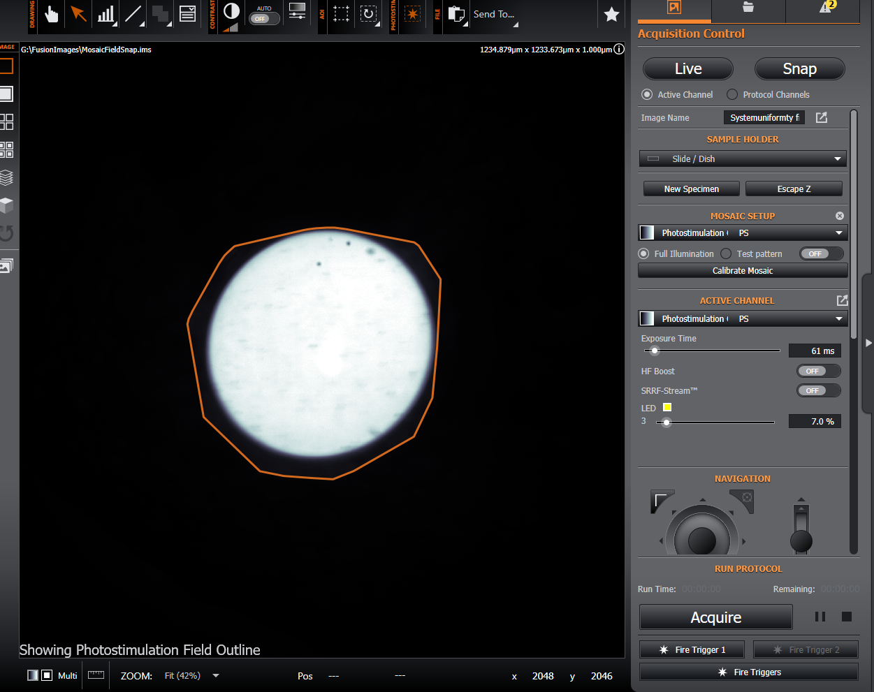
Review the calibration using the Photostimulation Field outline as a reference. A successful calibration should have a smooth and clear outline as shown below. The size and extent will vary depending on the illumination source and Mosaic model - it may be either circular (as below), or rectangular with rounded edges.
If the calibration has failed for some reason please refer to the following failed troubleshooting guidelines.
Failed Calibration and Troubleshooting
It is possible that the calibration may fail to find the spot-shaped illumination patterns. Some troubleshooting examples are shown as follows:
Cannot see Test Pattern: Always check that the illumination path from the light source i.e. HLE, Mosaic Laser or LED, via the Mosaic, through to the detector (camera) is clear using the Test Pattern or Full Array. Check that the illumination source is connected and emitting ensuring that: suitable beamsplitter plugs and microscope cube are present Beamsplitter Plugs and Microscope Cubes for Photostimulation and selected so that the photostimulation wavelengths will reach the he sample. Also check that the Shutter for the Mosaic if present, is turned on, as otherwise it will prevent light reaching the Mosaic. If it is not set to trigger to open automatically on activation of the Mosaic, then set to Normally Open (NO) so that light passes through the shutter to the Mosaic and .
Calibration slide appears out of focus: It is important to focus on the calibration slide – ensure this is in focus on the specimen plane. The sharpness of the test pattern will also depend on whether confocal or widefield is used and the sample used for calibration e.g. a FRAPPA slide will provide sharper focus than a plastic fluorescent Microscopy slide.
Additional Reflections: If you are using a low magnification air objective with a LED/white light source you can get reflections off the coverslip and the first surface when using the Mosaic during setup and calibration and these passing through to the camera. This is due to the effect of these surfaces being within the working/focal distance for the objective. These reflections are not observed when using a higher magnification and/or high numerical aperture (NA) or oil immersion lens or when using laser light sources with discrete wavelengths. In use, the power density of such reflections within the sample are generally so low relative to the power at the focal plane on the specimen that it does not affect bleaching or induce photoactivation.
Insufficient signal: Ensure that the sample used for calibration has strong fluorescence. Check that the Mosaic illumination time and camera exposure in the calibration channel are long enough to allow for spot detection as this parameter is based on signal to noise detection. A good guide is a signal to background of 5:1. You can approximate this by hovering the mouse over the background, and the illuminated regions when the test pattern is displayed and determining the counts.
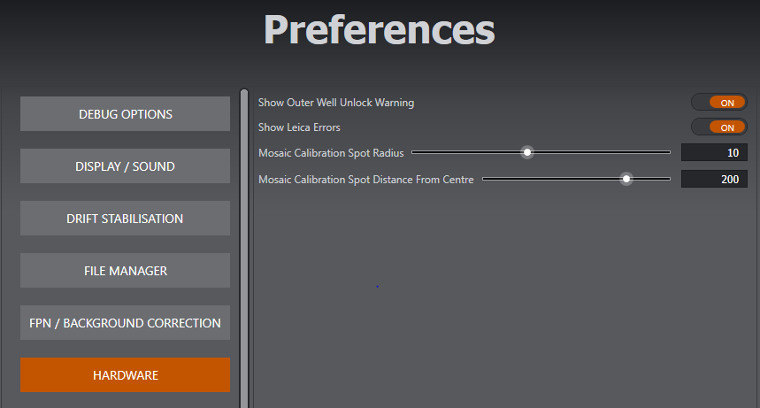
Very bright spots causing glow or distorted calibration area: Check that the signal is not too strong and saturating the detector. Reduce Mosaic illumination time and camera exposure time. If this is not sufficient, reduce the size of the spot radius for the calibration under preferences (see below). The recommended starting point is 10.
Spots appear outside the illuminated area: This is normally configured during initial installation. However, if this occurs, reduce the distance of the spots from the centre of the Mosaic. This can be adjusted under Preferences (see below).
Irregular Shape that does not match expected calibration region: The calibrated region should match that of the Mosaic and illumination source and thus have a defined and regular, smooth edge. If this is not the case ensure the signal to noise is sufficient (a good guide is 5:1). You may adjust the spot size slightly lower e.g. from 10 to 5 to allow a more precise outer region for the extent of the calibration. Also check that the laser intensity is not too high and causing excess glow/dispersed light outside of the DMD active area that will impact the calibration.
The default values for the spot positions (and spot radius) on the DMD may be updated via the Hardware Preferences section:
Photostimulation Field
The selectable photostimulation field can be displayed from the Photostimulation Tools section when calibrated. This acts as a guide when defining a photostimulation region (only the area within this field shall be illuminated by the current Mosaic calibration). Be careful when placing regions of interest so they do not fall outside the photostimulation, moving the region of interest within the available area, or moving the specimen so it is within the area.

Viewing the photostimulation field on completion of a calibration is also recommended to ensure that the completed calibration coincides with the Mosaic illumination as expected. The final output from the calibration process is an image showing the current illumination, so selecting the above button from the Photostimulation Tools section should result in the outline surrounding the shown illumination (as shown here for both full illumination and with the test pattern). If the outline does not surround the shown illumination then the calibration may have to be re-run after refocusing and/or increasing or decreasing exposure time or laser intensity.
Below are examples where the laser intensity had to be reduced before a valid calibration could be achieved.
Invalid:
Valid Calibration - not the Photostimulation outline matches the illuminated area and has a smooth and regular outline.

Proceed to setting up a Photostimulation Protocol: Creating and Running a Photostimulation Protocol
Please refer to the video tutorials outlined here for further help: Calibration